
In the mountains of New Mexico the temperatures vary quite a bit during the year. Summer overnight lows are typically in the mid-60s, while winter lows are usually in the mid-teens. Telescopes expand and shrink with these temperature changes. It turns out that the telescope mount also changes a little. The result is that the mount’s drive gear mesh needs to be adjusted to optimize performance for summer or winter operation.
In the case of my Titan mount, there’s a sweet spot in the gear mesh tension for best performance. If the mesh is too loose then excessive backlash degrades guiding performance. If the mesh is too tight then the motors have to work harder and may even stall or overheat. Adjusting for the right mesh tension has been a try it and see how it does game.
Enter my latest project: the Telescope Mount Power Monitor. This device displays the voltage and amount of current the mount is using. Knowing how much current the mount’s motors are using can indicate how hard they are working. So when adjusting the mount’s gear mesh watching for the point that the current starts to increase indicates “that’s tight enough”!
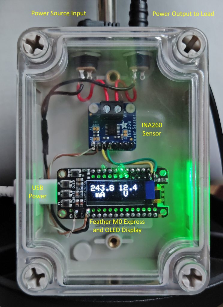
The monitor consists of three modules: a Feather M0 Express microcontroller, an OLED FeatherWing display and the INA260 Power Sensor. All the modules come from Adafruit. The software is written in “C” using the Arduino environment and is based on the example code that Adafruit provides. The total cost of the project was about $60.00, plus my labor of course.
The Monitor is placed in series with the mount’s power source and gets its own power from any USB power supply. The display provides real-time readouts of the current the mount is drawing and the supply voltage level. Hopefully, this tool will ease the gear mesh adjustment process this coming winter.